How Valve Actuators Work: From Signal to Movement
INTRODUCTION: TURNING COMMANDS INTO CONTROL
In modern industrial systems, valves rarely operate by hand alone. Instead, they are controlled automatically using actuators — devices that convert a control signal into physical movement. Whether it’s opening a valve to allow flow, closing it for safety, or positioning it precisely for control, valve actuators are what bring automation to life.
Understanding how valve actuators work — from the moment a signal is sent to the moment the valve moves — is essential for anyone involved in industrial systems, automation, or maintenance. This guide explains the process clearly, step by step, without unnecessary complexity.
STEP 1: THE CONTROL SIGNAL
Everything starts with a signal. In automated systems, this signal usually comes from a control system such as a PLC, DCS, or control panel. The signal tells the actuator what to do — open, close, or move to a specific position.
Signals can be electrical (such as 24V, 110V, or 230V), pneumatic (air pressure signals), or digital (bus systems and feedback loops). For control applications, analogue signals like 4–20 mA are commonly used to achieve precise valve positioning rather than simple on/off operation.
At this stage, nothing has moved yet — the system has simply issued an instruction.
STEP 2: ACTUATOR ACTIVATION
Once the signal reaches the actuator, it triggers the actuator’s internal mechanism. How this happens depends on the actuator type.
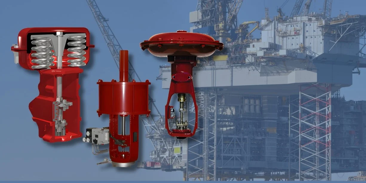
In pneumatic actuators, the signal opens a solenoid valve that allows compressed air into the actuator chamber. The air pressure pushes against pistons or diaphragms, creating mechanical force.
In electric actuators, the signal powers an electric motor. That motor turns gears or a drive shaft, converting electrical energy into controlled rotational movement.
In both cases, the actuator is designed to generate enough force or torque to overcome system pressure, valve friction, and sealing resistance.
STEP 3: MECHANICAL MOVEMENT
The actuator’s internal movement is transferred directly to the valve. This is usually done through a drive shaft or mounting kit, ensuring precise alignment between actuator and valve.
Rotary actuators are commonly used for ball and butterfly valves, turning the valve through 90 degrees. Linear actuators are used for globe and control valves, moving the valve stem up or down.
This stage is where signal becomes motion — controlled, repeatable, and powerful.
STEP 4: POSITIONING, FEEDBACK, AND SAFETY
In more advanced systems, actuators don’t just move blindly. Position feedback devices such as limit switches, positioners, or encoders confirm the valve’s status and report it back to the control system.
Safety features are also critical. Spring-return actuators automatically move the valve to a safe position during power or air failure. Torque limiters and overload protection prevent mechanical damage.
This feedback loop ensures the system always knows where the valve is — and that it moves safely every time.
WHY THIS PROCESS MATTERS
Understanding how valve actuators work helps prevent common issues such as incorrect wiring, undersized actuators, poor response times, or unexpected failures. When selected and installed correctly, actuators provide consistent control, improved safety, and reduced manual intervention.
Valve actuators are not just accessories — they are the link between digital control and physical flow.